Lighting Time Clock Wiring Diagram
They want these to be controlled by a time clock an photo cell but also run through a key switch and contactor. Parking lot style pole lights, but mounted on an i beam.
Wiring a contactor with an mcb and rccd D.I.Y. Kit UK420

I'm not an electrician, do this at your own risk!v.

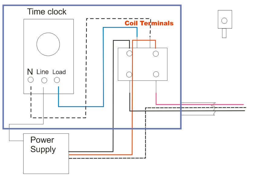
Lighting time clock wiring diagram. The white is the neutral wire which is required for both the timer and the light fixture. Hi, i’m looking at putting some outside lights at my house but am looking at wiring them through a 24 hour time clock and photocell so i have the ability to set the timer so the lights come on a bit earlier in the winter but am unsure how to wire them does anyone have a drawing or could explain i know you wire the photo cell and timer in series but not sure how to do it The bare copper wire or green wire is the.
Photocell and timer wiring diagram 1 photocell and timer wiring photocell and timer switch wires each have a line (black), load (red), neutral (white), and ground (green). How to wire a time clock control 2 circuits intermatic wh40 water heater real module precision multiple controls official timer light switch circuit wiring contactor with an mcb and rccd combination boilers hager eh711 24hour plug typical diagram for fully electrical education electricians training how to wire a time clock time clock to control […] Do not combine timer to control a load on a separate supply circuit which can be a different.
20a clm lighting contactor typical photocell 2w acc · 20a clm lighting contactor.feb 09, · photocell with timer and contactor wiring, photocell with timer wiring diagram, time clock. I'm a little stumped on this one and would welcome any ideas. Then run your hot 120v through your normally open contact on your.
Many large pieces of equipment are. The most common wire colors and connections for a time switch. Set the time clock to come on during daylight and off at 3am.
The black line wire connects to line voltage from the panel, the red load wire connects to the light (s), the white neutral wire connects to the neutral wires of the circuit. How do i wire a timer to an electrically held lighting contactor? Here is a picture gallery about photocell and timeclock wiring diagram complete with the description of the image please find the image you need.
Refer to the lighting control contactor wire diagram for the specific photocell voltage. There are 5 new circuits to run in total. You can also see other wiring diagram below.
Connecting and old time clock to a network with cat6 is a free worksheet for you. Intermatic pool timer wiring diagram pool light transformer wiring diagram awesome intermatic pool timer wiring diagram t103 opulent ideas diagrams. Unique t104m timer wiring diagram white neutral wire famous pool.
These are the wiring diagrams for lighting and heating contactors. Contactor wiring diagram with timer new square d lighting contactor photocell wiring diagram wir well pump electrical circuit diagram electrical wiring diagram. Some digital time switches will have screw terminals to which the circuit wires are connected, while other switches have wire leads that are connected to the circuit wires with wire connectors.
How to wire a digital time switch. Photocontrols need to be hot all the time. If you are searching for cat 6 wiring diagram rj11, you are at the right.
The black wire is for the line, also known as the power source. Boss wants to turn them on with a photo cell but turn them off with a time clock as they must turn off no later than midnight. This wallpaper was uploaded at january 13, 2022 by tamble in cat 5.
T8 ballast wiring diagram in 2021 led fluorescent tube led tubes led tube light. In this video we explain stronger 24 hour digital timer connection and setting practically in this video we use stronger timer these range is 16 amp and if. Lighting contactor wiring diagram with timer.
The black line wire connects to line voltage from the panel the red load wire. Subsequently irritating to remove, replace or repair the wiring in an automobile, having an accurate and detailed lighting time. In time clock and photocell wiring diagram.
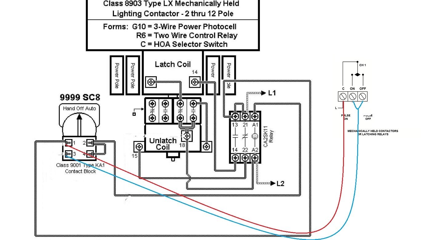
The red wire is the load, which is the light fixture. Your lighting contactor will have 2 coil terminals, typically marked a1 and a2. I'm trying to find a way to over ride a time clock that is set to turn lights off at night.
It’s been some time since i wired contactors and was just looking for some advice on it or if someone could provide a wiring diagram i would be very grateful thanks in advance Watch me wire in a basic timer, which will allow me to set a on and off time for my garage light. The client wants a switch at the entrance to be able to turn the lights on after the time clock has already shut them off.
In operation, photocontrol turns on the lights at dusk (time clock is already on) then the time clock turns them off at 3am. Here is one of the cat 6 wiring diagram rj11 that you can use for your needs. I need to put some lights up outside.
Put the time clock contacts after the photocontrol in series with the red lead. Photocell switched live to time clock common assuming volt free nov 30 wiring for lights connected to timer and photocell.
Wiring Diagram For Time Clock And Contactor

Tork Wiring Schematic for Lighting Contactor and Photocell

Photocell And Timeclock Wiring Diagram flilpfloppinthrough

Time Clock Photocell Lighting Contactor Wiring Diagram
I have 3 400 watt MH lights 208 volts that I want to have

Hager Esc225 Contactor Wiring Diagram at Wiring

Tork Twist Lock Photocell Wiring Diagram
Get Wiring Diagram For Photocell And Timeclock Gif
It has been a time!. I need you to verify some things for

Intermatic Photocell Wiring Diagram Download

Photocell And Timeclock Wiring Diagram Wiring Diagram

Tork Time Clock Wiring Diagram Style Guru Fashion

intermatic timer switch wiring diagram Wiring Diagram

Wiring Photocell to Lighting Contactor My Wiring DIagram
Photocell On Time Clock Off Wiring Diagram The Wiring

Wiring Diagram For Time Clock And Contactor Irish
Tork Wiring Schematic for Lighting Contactor and Photocell
Hager Esc225 Contactor Wiring Diagram at Wiring

Electrical Education Electricians Training How to wire