120v Electric Motor Wiring Diagram
These diagrams are current at the time of publication, check the wiring diagram supplied with the motor. It is a series wound motor.
120v Electrical Switch Wiring Diagram Wiring Diagrams
It runs but is slow to start and sometime needs help.

120v electric motor wiring diagram. Push down and it runs the other direction. Electric motor wire marking & connections. 120 volt motor wiring diagram.
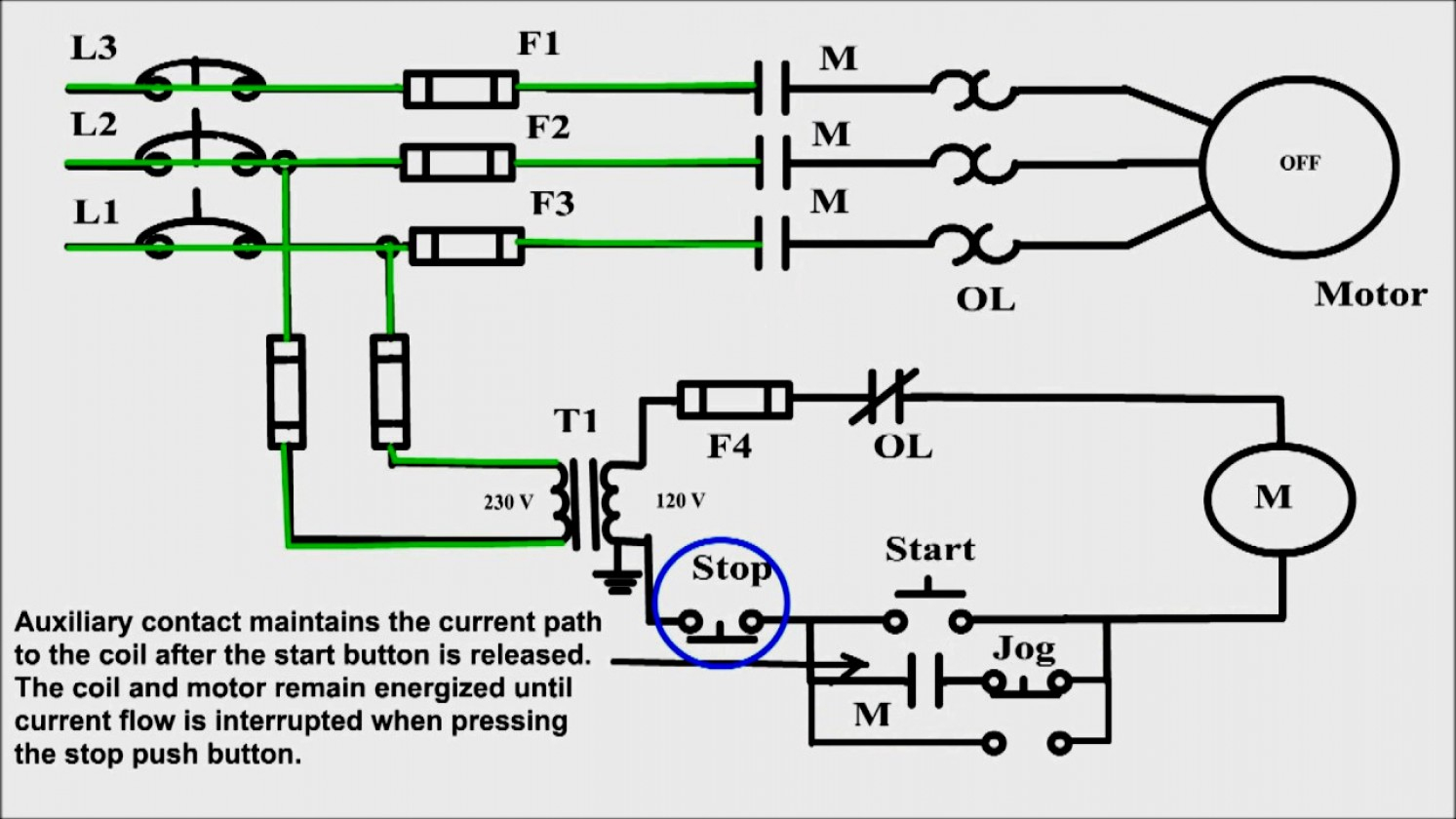
Feed the wires through the conduit from the receptacle box. I am wiring a 480 volt motor. Wiring diagram for a starter controlling a 480v motor with 120v startstop button.
To reverse rotation on a single phase capacitor start. Put a couple of pieces of electrical tape over the end of your wires, so the copper is not exposed. A universal electric motor is designed to operate on either alternating current or direct current (ac/dc).
Wiring diagram 120 volt motor electric diagrams three phase basic. Select a motor's 220v or 110v wiring setting by adjusting wires on the terminal plate. Reconfiguring between 240 and 120 volts is done the same way but the starter winding stays connected to one of the windings.
It is provided with a field winding on the stator which is connected in series with a commutating winding on the rotor. A2 goes to live wire. A balanced electrical load which may save on electricity compared to an unbalanced electrical load.
Refer to the motor manufacturer’s data on the motor for wiring diagrams on standard frame ex e, ex d etc. Active 2 years, 8 months ago. Wiring a 120/240 volt motor for 240 volts is as follows:
120v ac capacitor motor reversing switch wiring diagram. Most buildings in the united states have electrical service that can supply either 110 or 220 volts (v) at once, and most electric motors are capable of running on either the lower or higher voltage. Terminal markings and internal wiring diagrams single phase and polyphase motors meeting nema standards see fig.
10hp 1 phase v baldor motor hums, no. 5744b52 electric motor wiring diagram 110 to 220 library 120 240 volt vac 1971 triumph spitfire for schematics terry love plumbing advice remodel diy professional forum tk 6191 single phase on free kv 6567 schematic dlpf. Ask that they not flip any breakers or switches until you are finished.
With the help of frank from franks motor shop it is shown how to easily, safely and quickly to wire a 3/4hp electric motor in this video. The other lug of the capacitor goes to live wire. This way, if your wire touches an exposed live conductor while feeding it through, it won't short out or conduct the current back to you.
The advantages of a 240 volt motor. 120v plug wiring diagram source: When you make use of your finger or perhaps the actual circuit with your eyes, it is easy to mistrace the circuit.
1 trick that we 2 to printing a similar wiring plan off twice. 240 volt motors will have a stronger start compared to a 120 volt motor. Each part should be set and linked to other parts in particular way.
Airflow airflow airflow airflow * * these diagrams are current at the time of publication, check the wiring diagram supplied with the motor. Release and the switch returns to center off and the winch stops. Ask question asked 3 years, 9 months ago.
In case of wiring errors or unusual motor types, have fire extinguisher ready when turning the motor for the first time and be ready to unplug the motor if it hums instead of turning. We are going to use the motor in a system that will be controlled by some external equipment. Fiber optic cable electrical connections motor 3ct to v separate control * ot is a switch that opens when an overtemperature condition exists (type mfo.
Inst maint & wiring.qxd 5/03/2008 10:02 am page 6 Read wiring diagrams from negative to positive and redraw the routine as a straight line. Print the wiring diagram off plus use highlighters to trace the signal.
Dayton electric motor parts diagram residential power is usually in the form of 110 to 120 volts or 220 to 240 volts. B2 goes to a capacitor; Each component ought to be placed and linked to different parts in.
12 baldor electric motor capacitor wiring diagram wiring diagram wiringg net electrical diagram electrical circuit diagram diagram one capacitor is the starting capacitor and the other is the run capacitor. All circuits are usually the same ~ voltage, ground, individual component, and changes. A schematic diagram of a forward reverse control for a single phase split phase motor.
Inst maint & wiring_5.qxd 20/11/2015 11:37 am page 7 Viewed 990 times 0 \$\begingroup\$ i have an old westinghouse motor with a missing wiring diagram. Honestly we have been realized that single phase forward reverse motor wiring diagram is being just about the most popular subject right now.
The terminal block has four connections, two labeled as line. Longer life may be found due to a stronger motor, where as 120 volt motors may heat up more. For specific leeson motor connections go to their website and input the leeson catalog # in the review box, you will find connection data, dimensions, name plate data, etc.
A1 and b1 are connected together and go to neutral wire. I would like to simplify the current wiring diagram so that the motor direction can be controlled by a spdt relay. To complete a single phase motor direction change, you will need to motors go in forward and reverse depending on their wiring and the resulting magnetic field.
120 volt motor wiring diagram from 2.bp.blogspot.com.
120v Motor Wiring Diagram 27
Rescue Hvac Motor 120v 1/2 Hp Wiring Diagram
Wiring Diagram For Reversing A 120v Motor With Dpdt Toggle Youtube
How to connect 120v dc shunt motor to 240v ac supply? The motor has 2 red wires connected to the

ac How to Wire a 120V Dryer Motor for Use in Other Projects? Electrical Engineering Stack

120v 3 Phase Color Code 33
Wiring Diagram For A Starter Controlling A 480V Motor With 120V Start/Stop Button Database
Rescue 120v 1/2 Hp Wiring Diagram
Rescue 120v 1/2 Hp Wiring Diagram

[DIAGRAM] Hitachi Jet Single Phase Electic Hoist Connection Diagram And Instructions Manual FULL

120v Ac Wire Colors MERAH268

Getting reverse to work on a 120V splitphase motor with a drum switch The HobbyMachinist

Unusual 120V AC Induction Motor Wiring Colors AskElectronics

120v Motor Wiring Diagram Wiring Diagram and Schematic
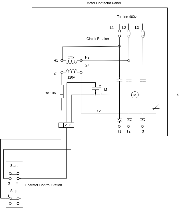
Wiring Diagram Fir A Starter Cintrolling A 480V Motor With 120V Start/Stop Button Database
Hvac Blower Motor Rescue 120v 1/2 Hp Wiring Diagram

Rescue 120v 1/2 Hp Wiring Diagram

Wiring Diagram For 120v Coil Contactor Complete Wiring Schemas
120v Plug Wiring Diagram